Technical Direction for Compositing Process Blog
- a
- Jan 7
- 22 min read
Updated: Mar 9
This blog post will serve as a process blog for multiple projects that I will be developing and completing in accordance to SCAD's VFX 420 Class: Technical Direction for Compositing, taught by Professor Bridget Gaynor. The post will be broken into 3 sections for 3 projects, all having their own updates that will be posted in chronological order, with the older posts and projects at the bottom, and newer at the top. Projects are separated with a double line divide, whilst updates are separated with a single line divide. Quick Click Links to each Project Blog Section: Project 1
Project 3: Magic Box and Projections
Criteria -
The primary purpose of this project is open a "box" that reveals assets that are entirely computer generated. Sometimes dubbed the "talking animal project" you will “open” an object that already exists in the live action plate that you create. Through the use of projection texturing, render layers and compositing, as well as other integration techniques, you will recreate the area that is revealed when you “open” that object. Work must incorporate several of the fundamentals that we've talked about in class.
Motion of objects inside are a bonus.
Requirements -
Photography/Camera/Composition
You will need to film an environment to use as your background with a real box in it. The portion of the box that will open should be at least 25% of frame.
You will need all of the reference photography from a photoset as established earlier in the quarter.
Subtle camera motion is required and must use a tripod. Camera motion must be tracked by you.
Please keep in mind that the box in your live plate will later move in CG. For example a door, a lid on a box, etc. must open. The photo alone should be visually strong and something you would include on your demo reel.
Motion
At least one object/box in your photographed environment will be animated to open in CG and use a projection texturing technique taught in class.
Animation of box opening should take approximately 2-4 seconds.
Modeling
You will need to create simplified proxy geometry for the CG object to interact with the environment of the photograph.
You will also need to create geometry for the part of your object that is revealed.
Any assets that are inside of the box can be sourced from the internet but must be cited.
Materials
Must be created entirely by you.
Reference is required and must be from the real world
Please avoid glass, transparent, or translucent objects.
Integration
Complete integration is required and all objects must look photorealistic.
Final composite must achieve a rendering quality that is the equivalent to what you would see in a photograph of the real world.
As the object opens you must show a shift in lighting that is accurate to the scene as the lid reveals what is inside.
Renders must be free of artifacts such as anti-aliasing, matte edges, and geometry faceting.
Video Submission
All rendered frames should be submitted in one video. Elements should be shown in a breakdown with each frame held for 1 second. No dissolves.
You should include a slate that has your name, the course name, "Winter 2024", and "Project 3".
Breakdown
Include the original photo and reference photos
Show the side by side of the grey ball reference match
Show all texture painting, material networks, uv layouts, and lighting and compositing techniques that are used.
Show the camera tracking with markers in place.
FINAL BREAKDOWN:
Week 9: 3/7/25 (Magic Box Inside Creation + Plate Clean Up)
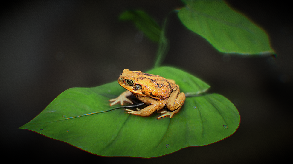
After getting the 3D tracking in order, I created the magical contents of the box. I wanted to do a pond scene where I had a frog sitting on rocks, surrounded by small plants and animated water. I also included an animated fish.

After getting the contents in the box correct (making sure the animation of the water was not too distracting or rough, and changing the color of the fish so it could be visible), I had changed the inside color of the box to be a cream white so that box inside could be better differentiated. I then added in the shadow of the box by using a shadow matte. I had sculpted the ground plane so that the shadow would have shape:


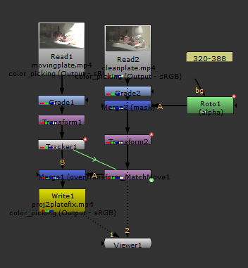
Next, I worked on cleaning up the plate. I realized I had to do multiple masks for different areas of the plate, since it was a moving plate and the placements / perspectives of the objects I needed to clean up all varied.

I tracked each individual area and created a transform match-move so that the masks would move correctly with the plate/ camera. I also created a fake shadow on the vase so it would look visually correct.


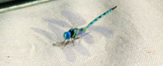
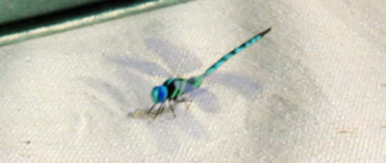
I then added an animated dragonfly to the scene! I did add some motion blur to it to make it look like it was zipping through the scene, and I did a quick mask so it looked like it was flying in around the incense stick that the bear was holding:


When the dragon fly landed on the ground, I used a shadow matte for it to create its shadow, but I also rendered out a caustics layer so that the wings’ shadow would have some color as they are translucent. I also added motion blur to match it’s wing movements:


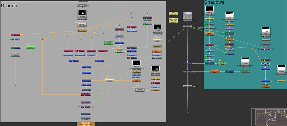
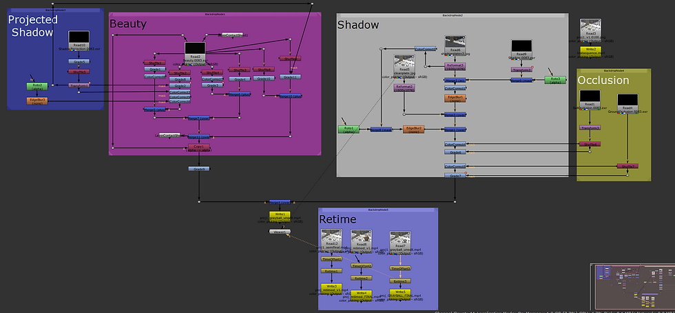
Here is the final Nuke script:


Here is the final breakdown (also included at the bottom of the Project 3 brief):
Week 9: 3/2/25 (3D Tracking and Projection)
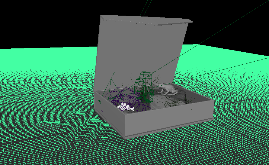
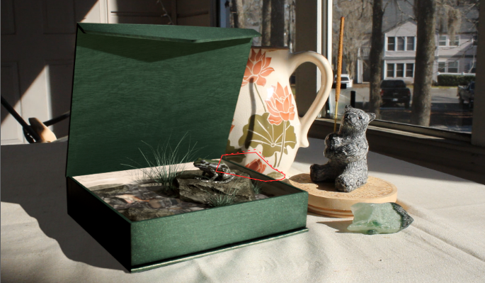
Continuing on with the project, I 3D tracked my plate and put in a red box to show where the placement of my object would be (as the dark green was hard to see). I then exported the camera fbx (with the placed box) into Maya.
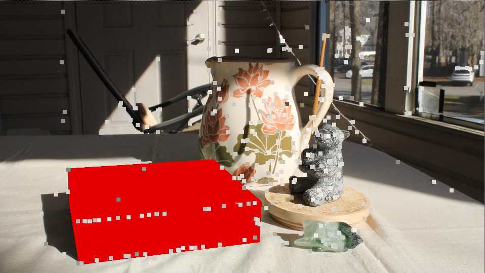
3D Track with placed red box in Nuke
By having the box within the export, this allowed me to see where the box was in relation to the 3D track. I then matched up the box from the fbx export with the box in my Maya scene. Now that my 3D Track camera was in place, I started on the projection part of the project.

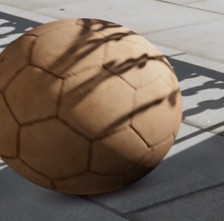
Image projected onto box geo

Image projected box geo render on top of image plane
After modeling the box (with a separate lid and flap), I had the box set up in relation to my RenderCam, so when I projected my image onto the box, it would line up correctly (above). Though it wasn't perfect, I tweaked it so that it wouldn't show the background. I then created a shader for the inside of the box, using a wood shader from PolyHaven to imitate the pattern that was on the outside of the box. I just changed the color to green within Maya. After transferring the maps to the animated box, I rendered it out and comped it together:

Wood Texture from PolyHaven
Comp with 3D Track
My next steps are to fix the track slipping, use a clean plate to cover the original box, render out a diffuse / specular version of the box for comp, and to render out an animation to use for an object inside the box.
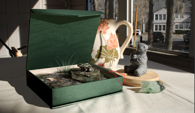
Week 8: 2/26/25 (Shooting Plates)
To kick off Project 3, I began by shooting my own plates:
I also took a video of the box opening to reference how the light effects the box:
Here are the images:


I haven't fully decided on what I wanted to come out of the box just yet, but I am thinking of maybe a still toad:
Model sourced from Sketchfab:
Or maybe chocolate frogs (sourced from Sketchfab:

If I went with the chocolate frog, I may attempt to follow this melting tutorial so that the frog can melt when the box opens:
Project 2: Camera Tracking (2a) and Customized Elements (2b)
For this Project, we will use elements of camera tracking and creating hybrid reflection, refraction and translucency elements in 3D to better integrate CG assets onto a live action plate. Here are the project requirements: Objective
P2a - Camera Tracking
Through the use of camera tracking, students will better integrate CG assets into a live action plate. This fundamental skill is essential for all VFX artists.
P2b - Customized Elements: “Reflection, Refraction and Translucency”
Through the use of creating hybrid reflection, refraction and translucency elements in 3D, and the implementation of them, you will further advance your knowledge of integrating elements in compositing. We will explore elements created through the use of Arnold, as well as some additional Maya Software shaders that introduce the concept of reflection and bounce light. Integration is key therefore moving the object will prove that you have accurate integration. Descriptive use of buildup and breakdown elements is required.
Project 2 Resources:
You will need a more complex 3D object for this one. (Sorry, no spheres allowed.) Use of one of the "Stanford Models" that can be found in the dropbox Project2_Resource_Library.
Object must take up at least 25% of the frame.
Requirements for Project2a:
P2a Camera must move gently and be tracked. Camera should hold at the end for 2-5 seconds.
Must include a matching render of the gray ball reference that sits on the ground and feels glued to a specific spot.
Requirements for Project 2b:
Must use the camera from Project 2a.
Object should animate through the environment during the 2-5 second hold.
Object will also need to interact with their environment by casting shadows and reflecting back onto the environment therefore you will need to model parts of the environment where the object will interact.
Composite should show accurate integration into the live action plate.
Object must move through the scene showing an accurate change in shading attributes.
Renders should be free of artifacts such as sampling noise, faceting, and anti-aliasing.
FINAL RENDER:
BREAKDOWN:
Week 6: 2/15/25 (Final Comp)
For the last two weeks, I had lost my original Nuke Script so I had to start my comp over. I did get to add some more elements such as another volume layer and caustics within the shadow mask, but it doesn't look quite as exactly as I had it. Render times kept being excruciating long, so I had to lower samples to get all my renders done in time. I do hope to rerender however, as the noise is really bad that even a simple denoise node could not fix it.
Here is the final comp and breakdown, also included above:
Final Comp and Breakdown
Here is my Nuke Script:
Project 2A + 2B Nuke Script
As you can see, many new additions. Since my last update, I did adjust some color correction, and added another volume layer:

Volume Layer 2

Volume Layer 2 After Adjustments
I also thought the horns and legs facing the camera looks too dark and dirty, so I did separate roto masks for each section and color corrected and graded them.

Roto Mask 1
Roto Mask 1 After Color Correction and Grade

Roto Mask 2
Roto Mask 2 After Color Correction and Grade
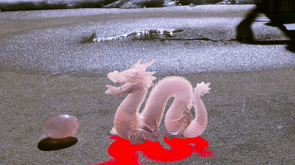
I also added in the shadow mask, which allowed me to color correct it and create a black shadow, but I also used it as a mask so that I could use my caustics ramp and shadow render within it.
Shadow Mask
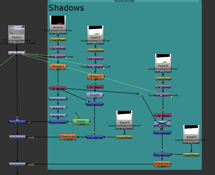
Close Up of Nuke Script for Shadows
Using a sharpen node, then shuffling the red channel to alpha, it allowed to to create a faked caustics shadow without color:

I then used the actual caustics render that had pink color, as well as the caustics ramp render to merge IN within the shadow mask to create the same look as the real crystals shadow within the live plate. I did two of these, one color corrected to yellow, and one with pink.

Yellow Caustics
Yellow and Pink Caustics
For the pink caustics, I did turn off the invert node that I used for the yellow caustics, only so that the pink could fill in areas that wasn't already affected by the yellow caustics layer and that they wouldn't have to compete with each other.
Though this is just a brief update to what I added to my comp since the end of Week 4, my official breakdown video definitely shows all of the work that I did for this render. Please be sure to watch that (click here to watch)!
Week 4: 1/31/25 (Shaders)
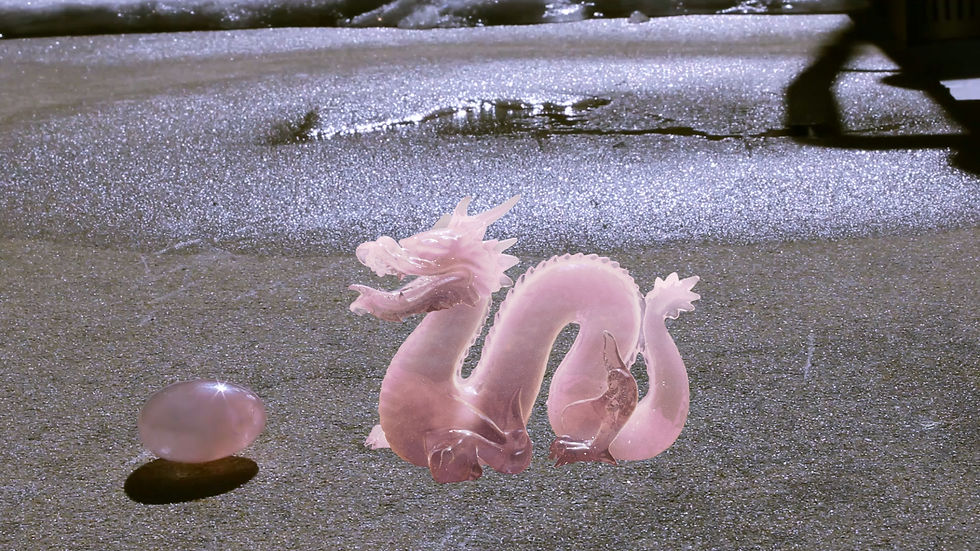
This week I focused on finishing up the scene set up, and adjusting the rose quartz shader. The last step for my scene set up was to match the CG Gray Ball light ratio to my reference image. Here are the results of that:
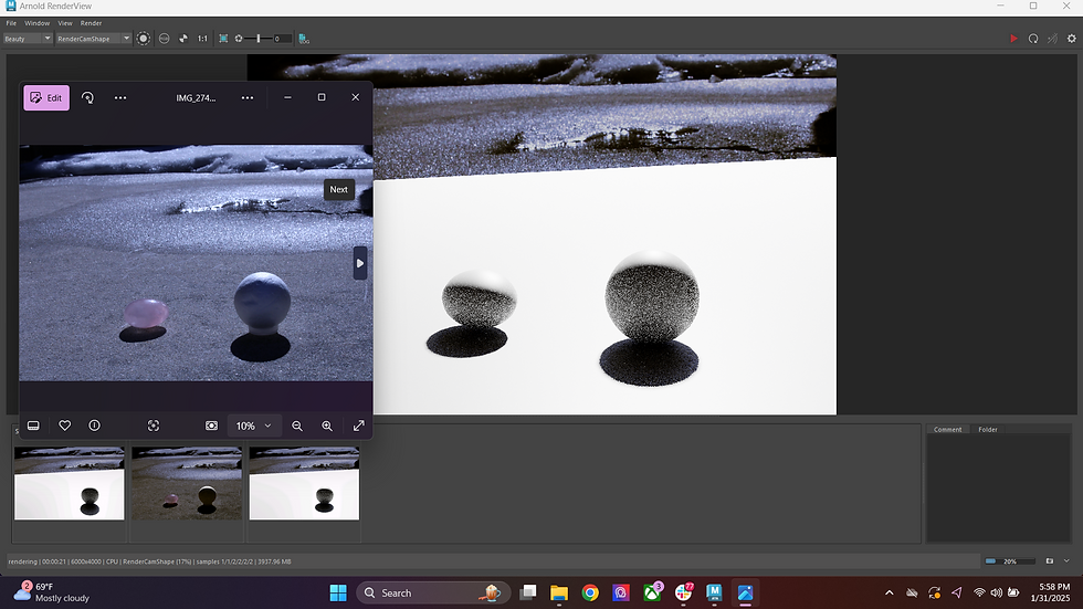
CG Gray Ball Set Up
This time I paid very close attention to the direction of the shadow (so adjusting the placement of the Sunlight), and the key to fill ratio on the CG Gray Ball. I made sure to pull up the reference image to see if both the factors matched with the original. I also placed a stand in object for where the crystal from the live plate was to also see if that shadow matched. After doing this, I began adjusting my Rose Quartz Shader.
Here are some reference images that I took of my personal rose quartz against and in the light:

Rose Quartz Backlit 1

Rose Quartz Backlit 2

Rose Quartz Under Sunlight
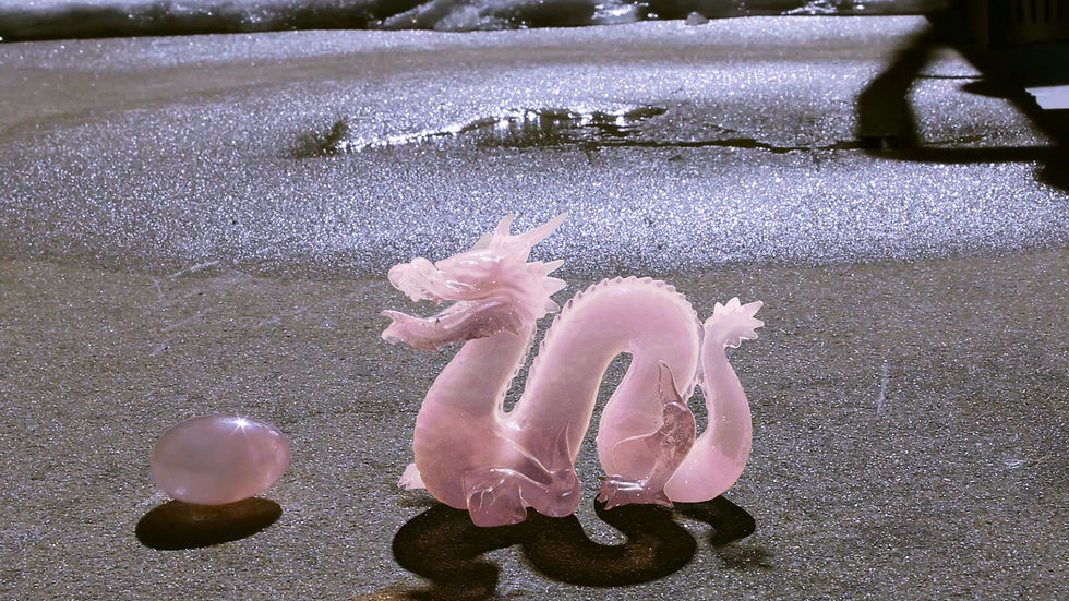
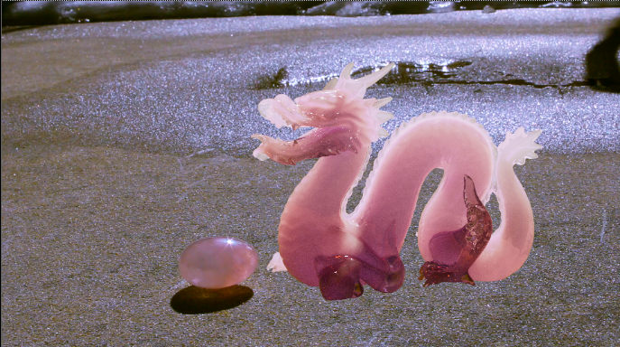
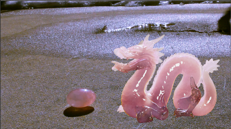
I also switched my model to the Stanford Dragon Model, as this is what my rose quartz shader was looking like when it was on the Lucy Stanford Model. I decided though it was a pretty model, it just didn't have enough surface area that I needed to show off the shader work:

Lucy Model with Rose Quartz Shader Base
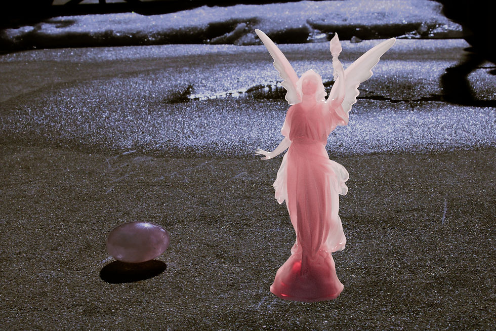
Shaded Lucy Model Slap Comp
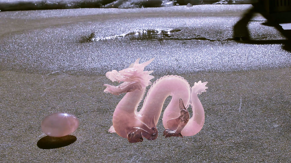
This is the "base" of the rose quartz shader on the Dragon Model, where I once again adjusted transmission and subsurface attributes:
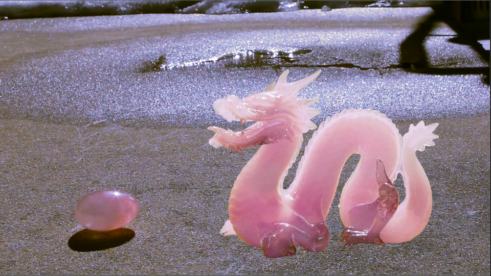
Rose Quartz Shader Base
This is a comp of the model with the plate with adjustments using AOV layers (tweaks in coloring):
Test Comp Using AOV Layers

AOV Layer Contact Sheet
I then began creating a new element to add to the shader. I wanted to recreate the cloudiness of the Rose Quartz - I used an aiVolumeShader within Maya, and added the Marble 3D Texture to it to create these two options:

Pink and White Volume Shader
Pink and White Volume Shader Comp
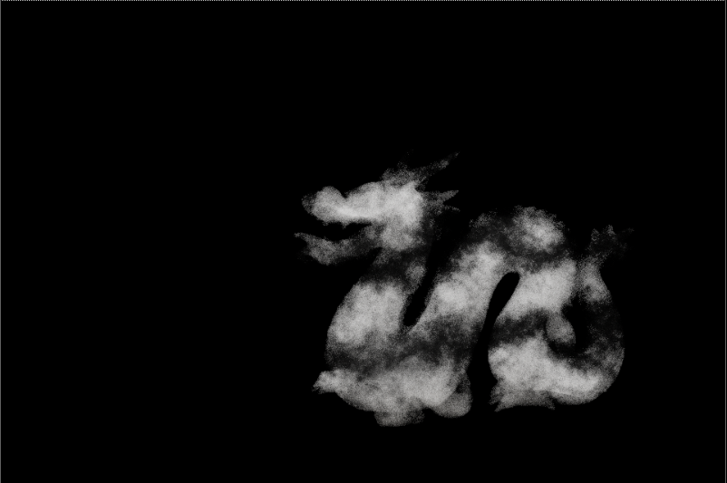
Black and White Volume Shader

Black and White Volume Shader Comp
I personally liked the black and white shader more, as it gave the crystal more depth - I also color corrected it to be slightly blue so it would match the crystal in the plate.
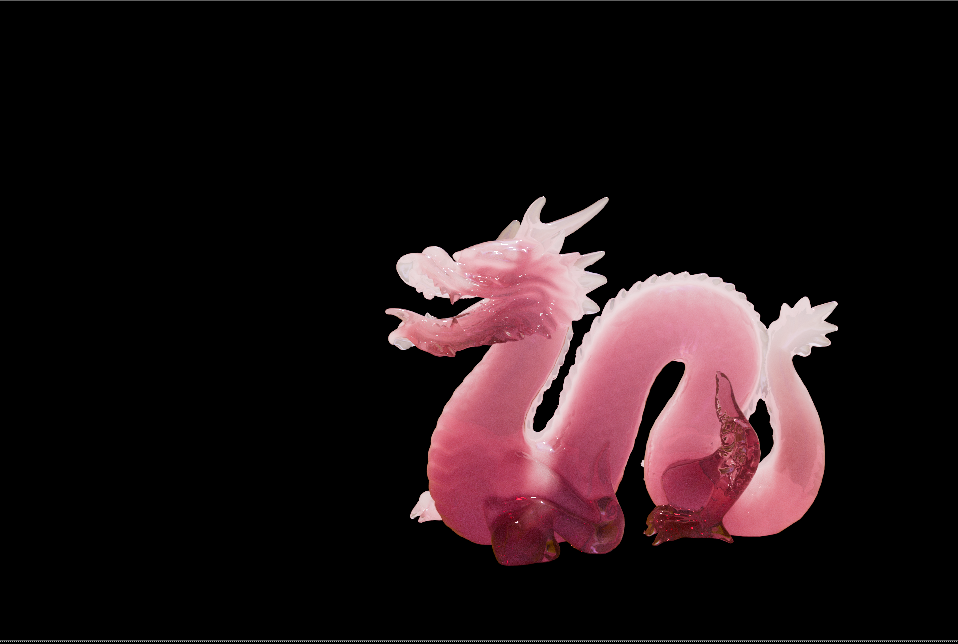
The next step was to add more specularity to the Dragon. I did several tests:

Dragon with Glass Shader
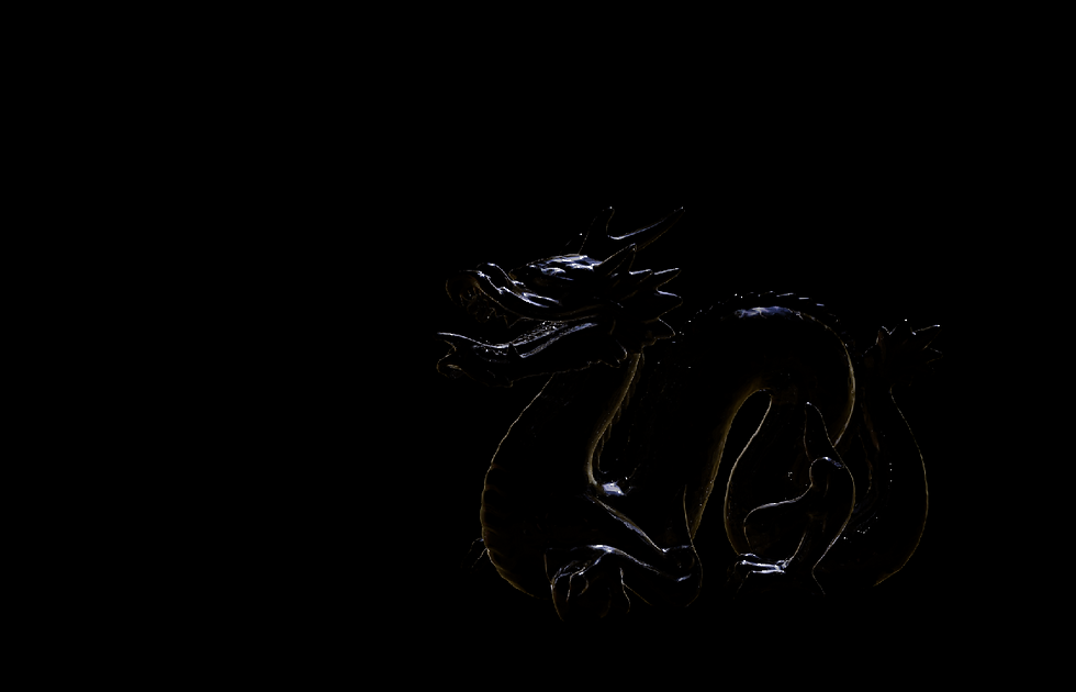
Dragon with Glass Shader (Specular AOV Layer)

Fresnel Shader

Reflective White Plane placed in front, Dragon Glass Shader with 0 Roughness
Reflective White Plane placed in front, Dragon Glass Shader with 0 Roughness Comp

Reflective White Plane placed farther, Dragon Glass Shader with 0.2 Roughness

Reflective White Plane placed farther, Dragon Glass Shader with 0.2 Roughness Comp
Though I wanted a bit more reflection, I didn't really like using the white plane to fake more reflections, it did not feel natural since the reflection was in the front and the scene is backlit. I ended up getting rid of the faked reflection, and added a small amount of glow in Nuke to emphasize the small specularity that was left.
The last step was to add in a shadow:
Shadow Matte Render
After adding in the shadow and color correcting it (only because we forgot to take a shadow plate during the shoot) , I added in the previous tracking that I prepped and here is the final result of the comp:
New Comp

Current Nuke Script
I will say the tracking is an issue, and I am still missing the caustics "glow" within the shadow. I also do plan on adding the streaks that show up in my reference crystal to the CG Rose Quartz Shader, but I am pretty satisfied with my progress so far.
I will continue working on this project, and hope to have the issues fixed soon.
Week 4: 1/28/25 (Restarting Project 2a, and Beginning Project 2B After receiving feedback from my Professor, it was decided that it was better to reshoot my plate instead of trying to relight it and mask out different areas on it. (When I did attempt this, you could see that the shadows were too different when trying to combine two plates into one).
Here are my new plates - the left images are the original, while the images on the right are the color corrected ones, as my camera was having trouble trying to do a custom white balance:


Plates Before (Left) and After Color Correction (Right)
I did keep the snowy areas a little blue, but I think I may keep working on the color correction - I was mostly focuses on matching the color of the ground to the moving plate. I will also adjust from feedback once I receive it.
Here is the original moving plate that I recorded (top) and the color corrected version (bottom):
Original Moving Plate
Color Corrected Moving Plate
I also tracked the moving plate to prep for Project 2B:

Screenshot of Tracking Moving Plate
Now that the plates were prepped, I began to set up my Maya file. I first began creating a test Rose Quartz shader (as that is my reference crystal):

Preliminary Rose Quartz Shader Test Render
I adjusted the transmission settings, as well as subsurface scattering. These models are also backlit to imitate what I will do when I set up the Beauty Object and Sunlight to match the live plate.
I am hoping to use this Stanford model as my Beauty Object, I just need to figure out where to get the .fbx version of it:
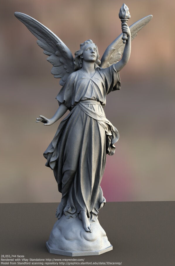
Stanford Model "Lucy"
The Stanford Model was sourced from this website: https://graphics.stanford.edu/data/3Dscanrep/
I also prepped my Maya scene in the same way I set up my Project 1 file:
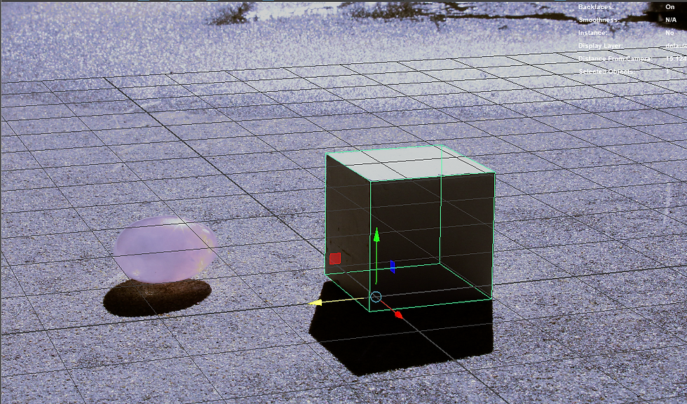
Cube Perspective Match (Wireframe)
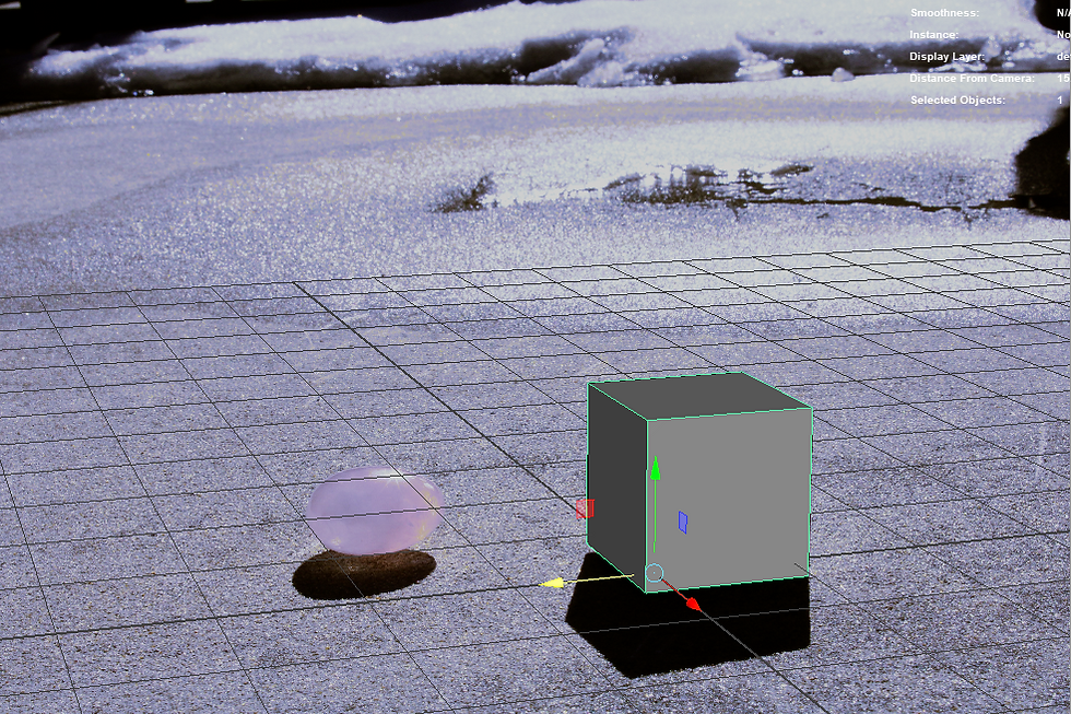
Cube Perspective Match (Shaded)
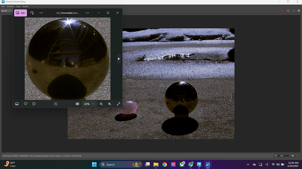
HDR Match/Line Up using CG Chrome Ball
^The original cropped chrome ball image is the floating window on the top left of the image, whilst the render with the HDR skydome reflection on the CG Chrome Ball is the bigger image behind it.
I also began prepping the render layers:

Render Layers Set Up
This week we will be focus on making the material of the Stanford Model match our crystal reference. Stay tuned for that!
Week 3: 1/20/25 (Beginning Project 2a - Shooting the Live Plate and Test Camera Tracking)
Today, I shot my live plate that included camera movement. I also took a still clean plate, grey ball, cube, and chrome ball images as well. I did have an issue with the sunlight moving rapidly within 30 minutes of me starting to shoot.
Here is the plate I took with camera movement:
Original Moving Live Plate
Here is the clean plate that I prefer (this was not shot with movement unfortunately):
Preferred Clean Plate
Within Nuke, I went ahead and roto'd out the area that I wanted, and masked it over the moving plate. I went to a frame where the positioning of the roto'd area matched up, and transformed it so that it would line it better. I then camera tracked two points within the moving plate, and match-moved it to my still plate.
Here is my Nuke Script:
Nuke Script of Camera Tracking
Here is the result:
Result of Camera Tracking
I am pretty happy with the result but I do have some things I want to fix next before adding the CG Asset in:
-Add still frames to the beginning and end to make the video longer
-Get rid of the stripy shadow to the left
-Comp in the moving fake flame on the candle during the still frames (using same method of camera tracking and roto mask)
Project 1: Lighting CG Objects through Compositing
For this project, we will learn how to control CG lighting using shadow and light passes with compositing techniques, as well as rendering 3D elements in layer passes. Here are the project requirements:
Modeling Requirements:
You will need a grey sphere that will be animated. It should look like the sphere that will be photographed with background reference.
You will also need to model an additional round object that has some detail.
Object will need to interact with their environment by casting shadows and reflecting, therefore you will need to model parts of the environment where the object will interact.
Object must take up at least 25% of the frame.
Project Requirements:
You will select a background element, HDR and reference photography from the Project1_Resource_Library.
You will match the camera in 3D, as well as the position and the value of key light and shadow
Composite should show accurate integration into the live action plate of both the grey ball and the other round object.
Object should move through the scene showing an accurate change in lighting and shadow.
Must show how elements are being used in a buildup.
All elements must be free of rendering artifacts such as sampling noise, faceting, and any other types of "noise".
I plan on shooting my own live plate and HDRI for this project.
FINAL RENDER:
BREAKDOWN:
End of Week 3: 1/23/25 (Final Render)
For the last week on this project, I focused on several things:
-Re-Animating the Beauty Object
-Rendering out the correct AOVs (and occlusion this time!)
-Rendering out an animated gray ball sequence
-Touching up on the overall look
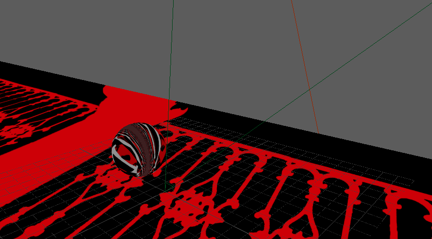
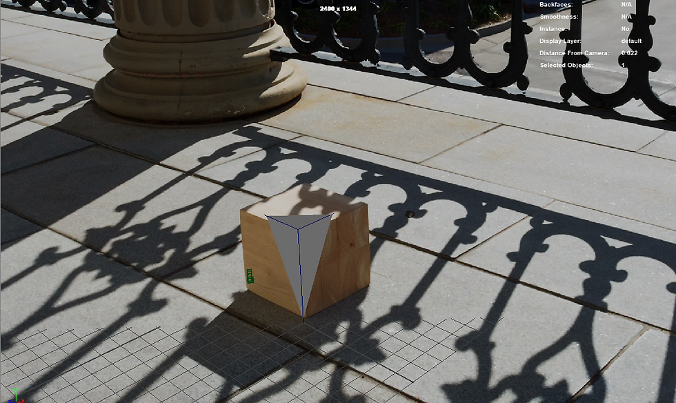
This was the semi final render (before I retimed it so the ball was rolling in instead of out):
Semi Final Render of Dirty Ball
I noticed a coupe of issues here, where the projected shadow was visible on the shadowed part of the ball, the ball was getting lighter in some areas, and that the ball wasn't in shadow when it was supposed to be.
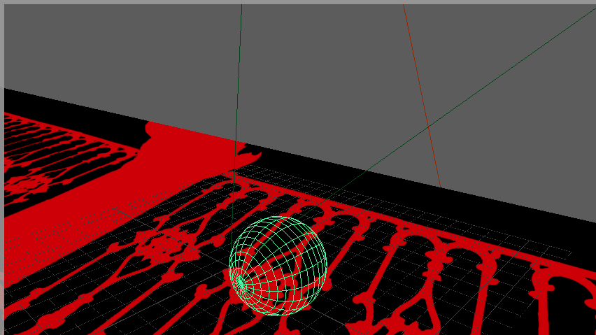
Here is an image of one of the issues:
Edge of the Ball was not in Shadow
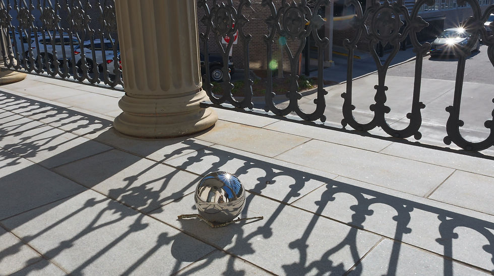
Here is the semi final render of the gray ball:
Semi Final Render of Gray Ball
The issue with this render was also with the shadows. I did have to roto some masks for both renders to get the shadows to behave correctly. Here is an example:

Roto mask for the Pillar Shadow
I created a mask to darked only the pillar shadow, as it originally was not matching and you could see a fine line between the shadows. I masked it out then color corrected the shadow. This is also how I solved the issue with the projected shadow appearing on the wrong areas of the dirty ball render. Other things I fixed:
-Keying the transform of the projected shadow, as it was not lining up with the object renders
-Re masking the pillar shadow on the ground so that when the ball passed over the area, the projected shadow lined up with the shadow on the ground
-Adjusted AOVs
-Keyframing the rotation of the shadows.
When you watch the semi final render of the dirty ball (above), I noticed that the ball's shadow was not following to same direction as the pillar's shadow:

Incorrect shadow direction
As you can see in the image, the ball's shadow begins to lean more left than the shadow's pillar, which is incorrect. I keyframed the shadow so that it would follow the sun's direction correctly:
Render with Keyframed Shadow
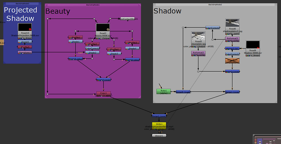
After finishing touches, this is what my Nuke Scripts looked like:

Nuke Script for Dirty Ball
Nuke Script for Gray Ball
The Gray Ball Nuke Script has a bit more because I had to account for specular indirect and specular direct AOV layers, as the Dirty Ball did not have specularity to it.
Here are how the final renders turned out (also at top of Project 1):
Retimed Final Render of Dirty Ball
Retimed Final Render of Gray Ball
Here is the breakdown for Project 1:
Project 1 Breakdown
Overall, I will say this project was very fun learning how to implement, use, and control AOVs. It had its moments of issues, but it was definitely interesting to see how many things I had to fix to make it look realistic. I am happy that I reanimated the ball, and I am pretty satisfied with the final image, but I am always ready to learn more!
End of Week 2: 1/18/25-1/19/25 (Fixes and Shadow Projection)
Today I worked on fixing the shadow plate, as I noticed that it did not line up with the clean plate. Here are the results:
As you can see, the cracks in the floor line up better now when the ball's shadow passes through them. I did have an issue with the shadow not blending in with the pillar's shadow when passing through it, so I did a quick roto and masked the shadow plate where the pillar's shadow is:

Shadow Roto
I copied and pasted the color correction node so that it would match. I feel as if this test shows the blend a lot better. I then created a shadow mask plate in Photoshop to project from the RenderCam onto the ground plane.

Shadow Mask Plate

View From RenderCam with Shadow Mask Plate Projected onto Ground Plane
Next, I created a camera from viewing through my Sunlight/Keylight. This is where I had issues.
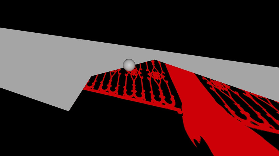
Shadow Projection Attempt, View from RenderCam
Test Render with Ghosting Ball Effect (Incorrect)
I figured out that I was not projecting from the right camera here, and I was also using the wrong image. It was giving a flat, ghosting effect as the sphere traveled through the scene.
I then tried using this image to project from the new SunlightCam:
SunlightCam Projection Image
It ended up giving me the wrong result. It had gray streaks and the red shadows were not lining up correctly:
Result viewing from RenderCam
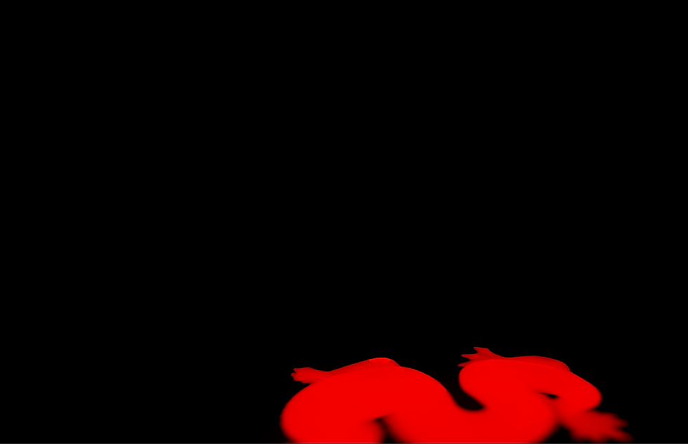
After consulting with some friends from the class, I learned that I was projecting an incorrect image. I was suppose to render without the sphere in the scene, and that I needed to fill out the rest of the image in Photoshop.

Attempt 1 at New Projection Image
After trying out the image above, that is when I learned I needed to fake the rest of the plate instead of blocking it with red. Here is the correct plate/projection image that I created in Photoshop:

Correct Projection Plate
I tested this new image by rendering it out and bringing it into Nuke. Here is the test render:
Shadow Projection Test Comp/Render
As you can see, the shadows are now reacting correctly with the ball.
My next steps were:
-Soften shadow as it stretches in Maya
-Bring in a new, realistic CG Object
-Animate CG Object
-Enlarge the cone angle of the Sunlight
-Render out in higher resolution
-Render out CORRECT AOVs (Need to separate out Diffuse Direct Sky, and Diffuse Direct Sun instead of simply "direct" lighting
Here are the results of all those fixes:
Correct and New Render!!!
Updated Nuke Script
As you can see, I brought in the correct shadow projection, and I no longer needed the edge blur for the shadow edges. And with the correct AOVs, the lighting and shadows look correct now! I did have to tweak some of the AOVs to match the lighting.
I will say that I am not a 3D Animator, but I am a lot happier with the new object render and comp. The lighting looks a lot more realistic, though I might render out a sequence where the ball rolls in instead of bouncing in, as I am not happy with how the bounces look.
I do believe the last step is to just add occlusion to the area between the ball and ground when they touch, so stay tuned for that!
Week 2: 1/14/25 (Testing AOVs and Comping)
Today I wanted to create a test Beauty pass with AOVs (Direct Diffuse, Indirect Diffuse, Direct Specular, Indirect Specular). I learned that the wooden cube used for my CG Camera match is actually 5 inches big, instead of the 2 inches that I entered in. However, when making the cube 5 inches, the scaling was too big to where I could not see the whole cube:
Clipping Issue
I decided to cut the scaling in half, and change the measurements to 2.5 so I could see the whole cube and correctly camera match. After that, I just realigned the Skydome to match the chrome ball image that was taken. The Ball on top is the CG, whilst the one that is mostly covered is the original.

Trying to match Skydome placement to ChromeBall Image
I noticed that the CG chrome ball was darker than the chrome ball in the image that was taken. I changed the intensity of the Skydome from 1 to 2, and achieved a matching look. Changing Exposure from 1 to 2 instead of Intensity also created the same effect.

Matching Skydome Exposure to Chrome Ball Image
I then realigned the Keylight (CG Sunlight) so that the shadow would also match the original image. The blue markings on the left pane in the image below are to show where the shadow is from the original image.

CG Shadow Matching
I then created the CG Gray Ball to begin matching the key to fill ratio of the CG Sunlight.

CG Gray Ball
I adjusted the intensity of the Keylight to match the ratio.

Key to Fill Ratio Lighting Match (Left Pane: Original Image, Right Pane: CG Gray Ball on Top of Original Image)
After I was satisfied with what I had as a test, I then animated a ball to roll through the scene. I rendered out a Beauty pass with AOVs, as well as a separate shadow sequence. I then brought everything into Nuke.

Nuke Script
I made some adjustments to the AOV layers, mostly just to mess around with them and learn how to adjust them. I also got to incorporate the shadow plate that I created earlier. Here is the final result:
Test Sequence Render
Though I am happy with this as a test, I believe I can keep working on it to make it look more believable. I do not want this as a final version.
Here are my next steps to improve:
-Fix Shadow Plate (cracks are not lining up correctly)
-Redo the Shadow renders (instead of using Edgeblur in Nuke, create the same effect in Maya)
-Change the Beauty Object and Animation
-Render higher quality
Week 2: 1/12/25 (Beginning of the Project)
I went with Sydney last week (1/8/25) to shoot our own live plates. I wanted the challenge of using a plate that hadn't been used already, and these are the images we ended up with!

Clean Plate
Chrome Ball Plate

Cube Plate

Styrofoam Ball Plate (In Place of Gray Ball)
However... we did forget to take a shadow plate image (where the area is completely blocked off from light so the entire ground surface is covered in shadow, used for integrating CG onto the cleanplate), so I had to create my own shadow plate!

Created Shadow Plate
I created the Shadow Plate using Photoshop, and this took a while as there were a lot areas that needed to be filled in. Though the Shadow Plate isn't perfect, I feel that with some adjustments in Nuke, I can make it work. The plan is to use masks from the CG shadow renders and pull from this plate, but not using full opacity. I will then either color correct or grade to blend the images together. We shall see if this works! But for now, I need to set up the scene in Maya.
Maya Screenshot of Cube Matching (Wireframe)

Close up of Cube Matching (Wireframe)

Close up of Cube Matching (Filled)
I matched it to the best of my ability, but I currently do not know the cube dimensions. Once I get the dimensions from Sydney (as she owns the cube) , I will make adjustments. I did know her focal length and camera used, which was 18 mm and the Canon Eos r7. After some research, the crop sensor for this camera was 1.6, so the camera focal length in Maya was calculated to 28.8, which is what I changed it to. (Same steps as in week 1!) I then switched out the projected image on the image plane to the chrome ball, and camera matched that. However, we also did not take a close up of the chrome ball in place. I had to crop the original wide shot of the chrome ball to use as an impromptu HDRI for the Skydome light to reflect off the CG chrome ball.

Cropped Chrome Ball Image from Wide Shot
Here is the CG Chrome Ball against the wide shot image.
CG Chrome Ball Test Render

Original Chrome Ball Wide Shot Image
I believe the main thing that is off right now is that the render is much darker than the original. The skydome is also slightly off. I will have to check my settings to see if I set up my Maya file correctly. I also wanted to set up the CG sunlight, so I created a ground plane to see the shadow. Here is my first attempt, left pane is viewing through RenderCam which is camera matched to the original plate, right pane is viewing through the CG Sunlight/directional light:

Trying to recreate the shadow on the CG ground plane

CG Cube on Original Cube Image Plate
The first image is the CG cube on the CG ground plane so you can see the shadow that I am trying to create, and the second image is the cube on the original cube plate that we photographed. Once again close, but I feel like I can make a few more adjustments to get it closer. The next steps are to fix the issues that I mentioned in this post (shadow matching, making sure Maya color space is correct, and adjusting skydome reflection / placement). I am hoping to also begin animating a CG sphere and test rendering layers as part of the project. Creating the shadow plate took a while, so hence my lack in new progress... but I hope to make up for lost time this week!
Week 1: 1/7/25 (Practice)
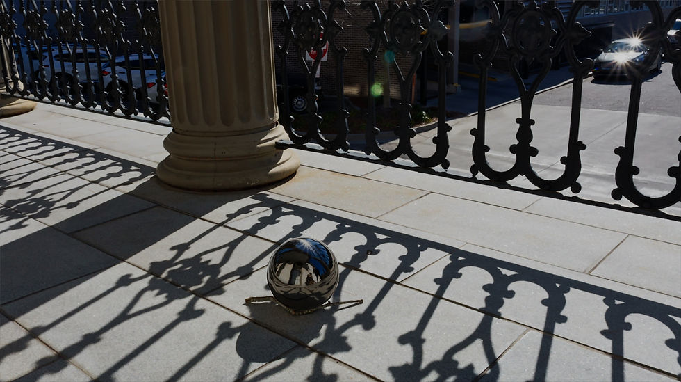
Though I have not shot my live plate and HDRI yet, I thought it was good to practice 3D camera matching using images that Professor Gaynor has supplied us. Here is the original image that I have chosen:

Image provided by Professor Gaynor, shot by Jung Woo Jin
Here is my CG Camera Match using a 2 x 2 x 2 CG square in Maya. The second image is Wireframe:

CG Camera Match with 2 x 2 x 2 Square
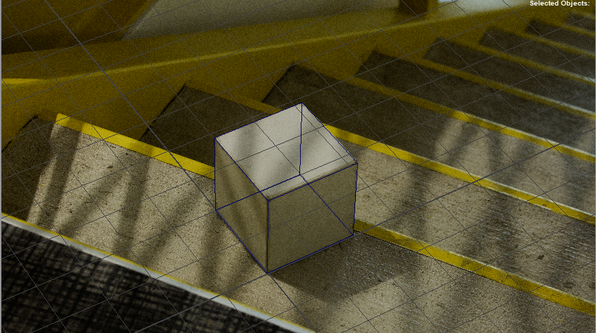
CG Camera Match with 2 x 2 x 2 Square Wireframe
To achieve this, I first looked at the original image's properties.

Image Properties
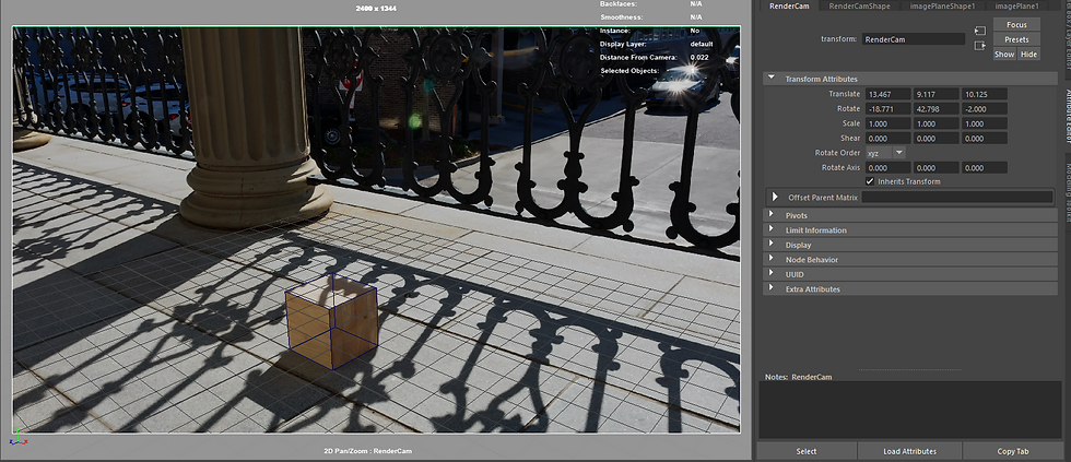
I made sure that my Render Camera in Maya had the same resolution as the image (5760 x 3240), then I looked up the crop factor for the Canon EOS 5D Mark. Luckily for me, the crop factor is 1, so I did not have to change the focal length of the camera There was no data for the 35mm focal length, so this is what I went with. Though it lined up pretty close, I ended up having to slightly tilt the actual camera on the z-axis, as tumbling was not enough alone to match the object.
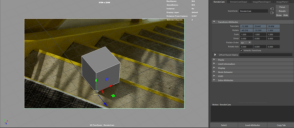
Screenshot of Maya Render Camera Transform Attribute
As you can see in the screenshot, I did change the pivot point to the corner of the square, and had it placed at the origin. You can also see the slight tilt on the z-axis in my Camera's Transform Attributes.
Though I believe this is an okay start, I plan to shoot my own plate and HDRI tomorrow!
Comments